DeformRF - Data-driven Beamforming and Direction Finding with Deformable Antenna Arrays
ACM MobiSys'26
Abstract
Low-frequency antenna arrays enable obstacle-penetrating communications, but their large physical footprint—a 4×4 array at 150 MHz requires 16 m²—prevents practical deployment. DeformRF enables portable, deformable arrays that compress to backpack-size yet maintain beamforming performance when deployed on flexible substrates. Our key insight is that data-driven methods can predict complex electromagnetic behavior under deformation without real-time simulations. DeformRF combines: (1) a 260,000-sample synthetic dataset mapping deformations to EM characteristics, (2) physics-inspired ML models achieving >94% prediction accuracy on average, and (3) smartphone-based 3D reconstruction requiring no infrastructure. In real-world experiments, DeformRF maintains beamforming gains within 1 dB of optimal despite severe deformation, while baselines degrade by 4–10 dB. For emergency response scenarios, our 4×4 flexible array achieves ±5° direction-finding accuracy when tracking signals through buildings.


The Challenge
Conventional antenna array design assumes rigid substrates with precisely controlled geometry. Many real-world deployments, however, involve surfaces whose shapes are dictated by external constraints—building facades, vehicle bodies, and curved architectural surfaces make mounting rigid, high-gain antennas physically impractical. This problem is especially severe at lower frequencies (≤ 2.4 GHz), where obstacle-penetrating communications demand large apertures.
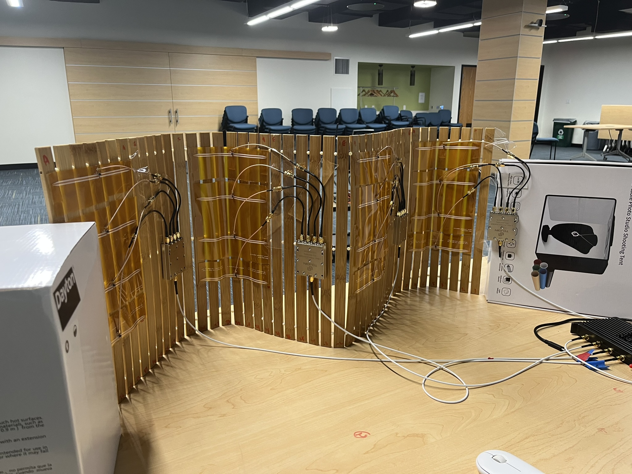
A fabric-based 4×4 array can be rolled into a 30 cm cylinder to fit a backpack, then rapidly unfolded and draped over any available surface. Yet this flexibility introduces a fundamental challenge: deformations alter electromagnetic (EM) behavior in complex, non-linear ways—simultaneously changing radiation patterns, impedance, and phase.

Key Challenges
Enabling effective wireless operation with deformable antenna arrays presents two significant challenges:
- Infinite deformation states — deformable substrates can assume virtually infinite configurations, making it impractical to pre-compute EM behaviors for all possibilities.
- Dynamic changes — deformations occur continuously during normal use as the substrate bends, folds, and twists, rendering one-time calibration methods ineffective.
Conventional EM simulations (e.g., Method of Moments) are computationally prohibitive—simulating a single deformed antenna can take several hours on a standard PC.
The DeformRF Approach
DeformRF is a lightweight end-to-end system with three core components:
1. Deform2EM Dataset
A comprehensive synthetic dataset of ~260,000 unique deformed antenna configurations and their EM characteristics, generated using Blender physics simulations and full-wave EM solvers. The dataset spans frequencies from 150 MHz to 850 MHz and covers both simple dipoles and complex Yagi–Uda arrays.

2. Physics-Inspired ML Model
A hybrid CNN–Vision Transformer architecture that predicts the complete EM behavior of a deformed antenna directly from its 3D geometry. Motivated by the computational structure of Method of Moments solvers:
- CNN branch (ResNet-Lite, 6 residual blocks) captures local geometric features.
- ViT branch (depth 8, 6 attention heads) captures global electromagnetic dependencies.
- Four parallel MLP heads predict radiation pattern, phase, polarization, and reflection coefficient (Γ).

3. Smartphone-Based 3D Reconstruction
DeformRF uses commodity smartphone cameras for one-time 3D capture of the antenna array, replacing expensive optical infrastructure. The pipeline:
- Spatial segmentation — isolates the antenna array from the background using tri-section clustering.
- RF element identification — locates antenna elements via RGB color anchoring.
- Curvature extraction — applies k-means clustering, hierarchical merging, and spline interpolation to recover each element’s precise 3D shape.

Key Evaluation Results
1. Beamforming Performance
Implemented 2×2 array: At low fold all methods exceed 12 dB, as the array is nearly flat. As deformation increases, DeformRF maintains consistent performance — outperforming DeformRF-PCA, Geometry, and Assume-Flat by >3.1 dB, 3 dB, and 4 dB respectively (a 3 dB gain effectively doubles array output). Prediction error stays below 1 dB across all fold states, while baselines reach 3–6 dB error under mid/high fold.
Simulated 5×6 array: DeformRF sustains ~30 dB gain across all 810 deformation configurations. DeformRF-PCA and Geometry drop to ~25 dB at mid/high fold; Assume-Flat falls below 20 dB. Prediction error holds at ~2 dB, while baselines exceed 5 dB as deformation increases.


2. Direction-of-Arrival Estimation
Indoor 4×4 array (850 MHz): DeformRF achieves ±5° DOA accuracy, outperforming baselines by more than 3×.
Outdoor-to-indoor emergency scenario: 4° DOA error — matching commercial rigid arrays despite deformation, and nearly halving the best baseline.


Key Contributions
- Deform2EM Dataset — First large-scale synthetic dataset (260k samples) mapping physical antenna deformations to full EM characteristics across 150–850 MHz.
- Physics-Inspired ML — Hybrid CNN–ViT model achieving >94% EM prediction accuracy, running in real-time on commodity hardware.
- Infrastructure-Free Sensing — Smartphone-only 3D reconstruction pipeline achieving sub-wavelength deformation accuracy without LiDAR or optical base stations.
- End-to-End System — Integrated beamforming and DOA estimation that maintains performance within 1 dB of optimal under severe deformation.